
| Instruction for preparing your single crystal samples |
Since phonon exists anywhere in reciprocal space, you need prepare single domain crystals for single crystal measurements. Sometimes the small domain can provide strong phonon intensity in some orientation, that contaminates the phonon spectra from the major domain (Fig.1). In general, the IXS spectrometer at BL35XU can not check whether the sample has a single domain. We recommend the users to perform a peak-search scan (embedded in the software) in the diffraction measurements at your lab (i.e., before coming to SPring-8), in order to confirm that your sample has a single domain. If the measurements tell you the multiple domains, you need to cut (or file or etch) the sample. In general, visual appearance (through eyes or microscopes) and normal 2θ-θ scans can not detect other domains.
|
| Fig.1 A minor domain can provide large phonon contribution to the detector.. |
If you perform an ω-scan in your lab, you will get the information of crystallinity (so called mosaic) as FWHM of a Bragg peak (Fig.2-1). Better quality (narrower FWHM) is preferred for the IXS measurements. In general, the width of Bragg peak recommended is less than 0.5 deg (at the BL35XU spectrometer).
Bad crystal quality can be confronted with the following issues.
⋅ You will not obtain the clear phonon structure in the vicinity of the Γ point.
In x-ray diffraction, in general, Bragg peaks appear at Γ. A broad Bragg peak yields the strong elastic peak even far from Γ, that covers the phonon feature (Fig.2-2)
⋅ You may not perform fine analysis.
The broadening of the Bragg peak is expected to give broadening of the phonon peak. You may discuss the positon of the phonon peak, but not the width.
 |
| Fig.2-1 An ω-scan of a Bragg peak. |
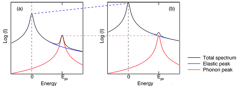 |
| Fig.2-2 Effect of a Bragg peak with (a) good and (b) bad sample quality. (a) if the sample quality is good, the elastic peak caused by the Bragg peak decreases quickly even close to Γ, You can identify the phonon peak at Eph. (b) If the sample quality is bad, the contribution of Bragg peak remains far from Γ, and the elastic peak has larger intensity than (a) at the same momentum transfer (blue dashed line). Since the phonon intensity is largely unchanged (red dashed line), the elastic peak easily covers the phonon peak at Eph . |
In IXS measurements, there are two geometries for measurements; transmission geometry (this geometry is often called Laue geometry (Fig.3a)) and reflection (Bragg, Fig.3b) geometry. While the transmission geometry can provide much freedom for sample rotation and tends to give more accurate experimental results. However, the geometry choice is mostly decided by the correlation between sample thickness (d) and x-ray attenuation length (λ) of the sample.
3-1. x-ray attenuation length
A sample has intrinsic x-ray attenuation length; some materials (consists of light elements) easily transmit the x-ray and other materials (including heavy elements) do not. Using the chemical formula and density of your sample, you can estimate the attenuation length (λ) from the following site.
https://henke.lbl.gov/optical_constants/atten2.html
Note, BL35XU utilizes Si(11 11 11) (hν=21.747 keV) or Si(999) (hν=17.794 keV)
3-2. Selection of the geometry
You can select the geometry from the following table
| λ > > d | (transmission (Laue) geometry (Fig.3a)) You may not obtain reasonable spectral intensity. |
| λ < d < 2λ | transmission (Laue) geometry (Fig.3a) |
| d > 2λ | reflection (Bragg) geometry (Fig.3b) |
3-3. A note for the reflection (Bragg) geometry
When the attenuation length (λ) is considerably short, x-ray can be blocked even by small humps, or roughness, at the surface. In such a case, you need to polish or etch the surface to get a flat surface. Note, sometimes these treatments will degrade the sample quality (mosaic) especially near the surface.
 |
| Fig.3 Measurement geometries. |
4-1. The lattice parameters are necessary and the atomic position is helpful for the setup procedure
The lattice parameters (i.e., a, b, c, α, β, and γ) of the material must be provided, in order to find Bragg reflections at the IXS spectrometer. Some small fluctuations for a, b, and c are adjustable, but wrong crystal symmetry leads to wrong reciprocal lattice units. In general, the IXS spectrometer can not estimate the crystal symmetry. The information of atomic positions in the unit cell is helpful, since this provides the intensity of Bragg peaks.
4-2. Before coming to SPring-8, please mount the sample on the sample holder and know two crystal orientations of your sample.
In addition to the lattice parameter above, (at least) two crystal orientations are necessary in the setup procedure, where correlation between reciprocal lattice unit and goniometer rotation will be established. The largest detector at the IXS spectrometer only have acceptance of a few deg. Hence when you do not know the two crystal orientations within several deg, we need to perform additional search.
Especially if you would like to see transverse modes with temperature dependence, the sample holder axis is preferred to be parallel to the crystal orientation giving the momentum for the transverse mode as possible(Fig.5). The IXS spectrometer at BL35XU has a 4x3 array. You can get the transverse phonon modes at 3 momentum transfers simultaneously, using the vertically-aligned 3 analyzers when this crystal orientation is aligned to the normal at χ(of the cradle)=0. For room temperature measurements, you can use goniometers (such as Huber 1002, 1003) to align that. However, there is no freedom in the cryofurnace for the measurements with temperature dependence.
The standard sample holders can be sent to the users on request. For room temperature measurements, you can use varnish or glue (epoxy) in mounting the sample to the sample holder. For low temperature measurements, you can use varnish or silver paste. For high temperature measurements, cement or silver paste may work.
4-3. Please prepare backup samples
Sometimes, the sample may unexpectedly drop from the sample holder during (or just before) the measurements. The backup samples, which are similarly mounted to the sample holders, will prevent wasting your beam time.
 |
| Fig.4 Reducing the angle between sample holder axis and the crystal orientation for the transverse mode (Angle A) enables effective measurements. |